 Russian
  English
  French
  German
  Spanish
  Polish
  Chinese
  Japanese
  Korean
 Содержание
Answer Excerpt
Mold venting in custom LSR silicone products should allow displaced air to leave the cavity before the silicone completely fills and seals the flow path. Vent locations are especially important at end-of-fill areas, deep textures, thin tips, narrow grooves and complex cavities. Gate position, venting, vacuum evacuation and product geometry should therefore be reviewed together during DFM before mold machining.
When liquid silicone enters a closed mold cavity, the material does not enter an empty space.
The cavity initially contains air.
As the LSR fills the product geometry, that air must move somewhere.
If it cannot escape effectively, the final product may show:
- Air traps
- Small bubbles
- Burn or discoloration marks
- Incomplete filling
- Missing texture details
- Short thin sections
- Surface marks
- Local flash
- Different quality between mold cavities
LSR equipment manufacturers therefore provide solutions for mold evacuation as part of silicone injection molding systems. ARBURG, for example, lists vacuum technology for evacuating LSR molds as part of its silicone processing solutions.
For OEM buyers, venting should not be treated as a minor mold detail.
It directly affects whether the product can be filled consistently at production scale.
What Is Mold Venting in LSR Injection Molding?
Mold venting provides controlled paths that allow air inside the cavity to escape as liquid silicone fills the mold.
Venting may work together with:
- Parting-line vent areas
- Dedicated vent features
- End-of-fill venting
- Vacuum evacuation
- Runner and gate design
- Mold inserts
The exact design depends on the actual product and mold.
The purpose is simple:
Air should leave the cavity without allowing unacceptable silicone flash to escape through the same path.
That balance is particularly important with LSR because the material can reproduce very fine mold details and can also enter extremely small gaps.
Therefore, a vent cannot simply be made “as large as possible.”
The venting strategy needs to provide effective air removal while maintaining controlled product edges and surface quality.
Where Do Air Traps Usually Appear?
Air traps often appear near the final areas reached by the silicone flow front.
Typical high-risk positions include:
- Thin product tips
- Deep recessed logos
- Narrow grooves
- Fine textures
- Tall bristles
- Closed pockets
- Sharp corners
- Thin outer edges
- Areas where two flow fronts meet
A product may appear simple externally but still contain several isolated end-of-fill areas.
For example, a custom silicone baby pacifier can contain:
- A thin nipple tip
- A thicker nipple base
- A shield
- Ventilation openings
- Logo details
- Ring or handle structures
LYA’s current pacifier product page also describes customization around nipple shape, shield structure, ventilation holes, logo, color and mold development.
Each feature changes how silicone and air move inside the mold.
Why Should Gate and Venting Be Designed Together?
The gate determines where the material begins filling the cavity.
Venting needs to support where the displaced air eventually travels.
Changing the gate position can change:
- Flow direction
- Last-fill location
- Air-trap location
- Flow-front meeting points
- Local pressure
- Surface appearance
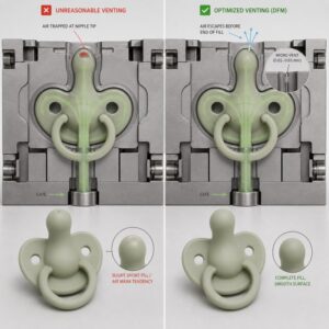
Consider a pacifier nipple.
If the silicone enters from the thicker base and flows toward the thin nipple tip, the tip may become an important end-of-fill area.
If the mold cannot remove air effectively from that location, the tip may show:
- Incomplete filling
- Tiny voids
- Surface defects
- Inconsistent geometry
This is why gate and venting should not be designed as two unrelated mold features.
They are part of the same filling strategy.
Why Are Thin Tips and Fine Details Difficult to Vent?
Thin product areas contain very little cavity volume.
Examples include:
- Pacifier nipple tips
- Spoon edges
- Thin sealing lips
- Small decorative ribs
- Fine bristles
- Narrow logo strokes
As silicone approaches these areas, the remaining air volume becomes increasingly small.
If the air cannot leave quickly enough, the silicone may stop before reproducing the complete geometry.
This can produce a product that looks almost correct but has:
- A rounded-off tip
- Missing small texture
- Incomplete logo corners
- Slight dimensional loss
- Weak local structure
The risk becomes greater when a thin feature is also far from the gate.
How Can Poor Venting Cause Burn Marks?
When air becomes trapped and compressed inside a small cavity area, the local molding condition can produce visible defects.
Depending on the product and process, the defect may appear as:
- Darkened spots
- Brown marks
- Surface discoloration
- Rough local areas
These defects are often concentrated near the end of filling.
A buyer may initially interpret them as simple contamination.
However, if the defect repeatedly appears in the same position on the same mold cavity, the engineering team should also review:
- Venting
- Flow direction
- Filling sequence
- Mold cleanliness
- Process parameters
Repeated defect location is useful diagnostic information.
Why Can Poor Venting Increase Flash?
It may seem logical to increase injection pressure when the product is not filling completely.
However, incomplete filling is not always caused by insufficient pressure.
If air is trapped inside the cavity, increasing the force used to fill the mold may create other problems.
Possible results include:
- More flash around the parting line
- Increased local deformation
- Greater pressure on thin edges
- A defect moving to another location
- More variation between cavities
The correct solution may involve improving the air-release path instead of simply increasing process pressure.
This is why molding defects should be investigated systematically rather than solved by changing only one machine setting.
How Does Vacuum Evacuation Help?
Vacuum-assisted LSR molding removes air from the cavity before or during the filling process.
ARBURG specifically lists vacuum technology for evacuating LSR molds within its silicone injection molding system options.
Vacuum can be particularly useful for products with:
- Complex geometry
- Fine details
- Long flow paths
- Multiple cavities
- Thin functional structures
However, vacuum does not replace good product and mold design.
A poorly positioned gate, difficult blind cavity or unnecessarily sharp geometry may still create filling risk.
The correct strategy may combine:
- Practical product geometry
- Suitable gate position
- Appropriate vent locations
- Controlled mold evacuation
- Stable process parameters
Why Does Vent Location Matter?
A vent located far away from the actual trapped-air area may have limited effect.
The engineering team first needs to understand where the material fills last.
Potential venting areas often need to correspond with:
- Flow-end regions
- Deep feature tips
- Texture extremities
- Thin peripheral zones
- Flow-front meeting areas
The final arrangement should be based on the real product geometry.
This is why custom silicone mold development should include a review of gate, flow path and venting before final tool machining.
Your current mold-development checklist already treats gate and venting locations as factors affecting air traps, incomplete filling, flow marks and surface appearance.
What About Pacifier Nipple Molding?
A silicone pacifier is a useful venting example because the product combines different wall thicknesses and highly visible surfaces.
The nipple may contain:
- A soft thin tip
- A gradually thicker body
- A wider base
- Fine transition areas
The silicone must fully reproduce the thin nipple geometry without leaving bubbles or incomplete surfaces.
At the same time, the final product directly contacts the user, so visible rough marks or uncontrolled flash are undesirable.
ENGEL has publicly demonstrated automated LSR production of a silicone nipple for a baby pacifier, illustrating that this type of product is a real precision LSR molding application.
During mold review, engineers should therefore pay attention to:
- Gate location
- Nipple-tip end-of-fill area
- Wall transition
- Venting
- Parting line
- Surface finish
- Demolding
- Cavity consistency
Why Can Venting Become Worse During Mass Production?
A mold may produce good samples at the beginning and develop filling problems later.
One reason is that very small venting areas can be affected by:
- Residue
- Contamination
- Mold deposits
- Insufficient cleaning
- Mold wear
- Maintenance condition
If vent performance changes, air may no longer escape as effectively as during the original sample approval.
Production teams should therefore monitor whether defects:
- Appear gradually
- Repeat in the same position
- Affect only one cavity
- Improve after mold cleaning
This helps distinguish a product-design problem from a maintenance-related venting problem.
Why Should Every Mold Cavity Be Checked?
A multi-cavity mold should not be approved using only one good product.
Different cavities may have slightly different:
- Filling behavior
- Runner balance
- Vent effectiveness
- Temperature conditions
- Gate behavior
ENGEL’s current LSR systems include high-cavity-count examples where precise cavity filling and process control are central to stable production.
During sampling and pilot production, parts should therefore be traceable to individual cavities.
Check each cavity for:
- Complete filling
- Air marks
- Surface quality
- Flash
- Product weight
- Critical dimensions
- Functional performance
What Should Buyers Check During Sample Approval?
Check End-of-Fill Areas
Identify the areas filled last and inspect them closely.
Inspect Fine Features
Check:
- Nipple tips
- Thin edges
- Logos
- Ribs
- Textures
- Small openings
Check for Repeated Defect Location
A defect that repeatedly appears in the same place may indicate a systematic mold or flow issue.
Compare Every Mold Cavity
Do not mix samples before cavity evaluation is complete.
Check Flash at Venting Areas
Venting should remove air without creating unacceptable excess material.
Perform Functional Testing
A visually acceptable product still needs to perform correctly.
For a pacifier, this includes checking:
- Nipple geometry
- Shield condition
- Surface smoothness
- Openings
- Shape recovery

LSR Mold Venting DFM Checklist
| Артикул | What Buyers Should Confirm |
| Gate position | Supports a controlled filling direction |
| End-of-fill areas | Identified before tooling |
| Vent locations | Positioned where air actually needs to escape |
| Thin features | Can fill completely |
| Fine textures | No trapped air at tips or grooves |
| Vacuum | Considered where product complexity requires it |
| Parting line | Venting does not create unacceptable flash |
| Surface areas | Critical cosmetic zones remain controlled |
| Mold cavities | Venting behavior is consistent |
| Maintenance | Vent areas can be cleaned and inspected |
| Образцы | End-of-fill regions are specifically inspected |
| Pilot production | Filling remains stable during longer runs |
How LYA Silicone Supports Venting and Filling Review
LYA Silicone provides OEM and ODM development for baby, pet, outdoor and educational silicone products, while its current product and OEM pages show support for mold development and silicone molding processes.
For LSR projects, engineering review may include:
- Drawing review
- Flow-path evaluation
- Gate review
- Venting analysis
- Wall-thickness review
- Fine-feature evaluation
- Mold design
- Sample production
- Cavity-by-cavity inspection
- Surface inspection
- Functional testing
- Pilot production
Venting is most effective when it is designed as part of the complete mold-filling system.
Frequently Asked Questions
Does Every LSR Mold Need Venting?
The cavity needs a way to manage displaced air, but the specific venting and evacuation strategy depends on the mold and product design.
Can Vacuum Replace Mold Vents?
Vacuum evacuation can improve air removal, but it should be used together with appropriate cavity, gate and mold design.
Can Poor Venting Cause Incomplete Filling?
Yes.
If trapped air prevents silicone from reaching an end-of-fill area, small tips, textures or corners may remain incomplete.
Why Does Only One Cavity Show Air Traps?
That cavity may have different filling, venting, runner or maintenance conditions.
Cavity-specific sample tracking helps identify the source.
Can Increasing Injection Pressure Fix Poor Venting?
Not necessarily.
If trapped air is the root problem, higher pressure can introduce flash or other defects without solving the underlying air-release issue.
Should Venting Be Reviewed Before Tooling?
Yes.
Gate, venting, thin features and end-of-fill areas should be reviewed during DFM before final mold machining.
Design the Air-Release Path Before the First Sample
Successful LSR mold filling requires more than pushing silicone into a cavity.
The mold must also provide a controlled way for air to leave.
Before tooling, buyers and manufacturers should review:
- Gate position
- Flow direction
- End-of-fill areas
- Venting
- Vacuum strategy
- Thin features
- Fine textures
- Mold cavities
- Maintenance access
To review the filling and venting strategy of your custom LSR project, send LYA Silicone your 3D drawing, material requirements, critical appearance areas, product dimensions and estimated production quantity.